CLIENT BUILD // OPEN SOURCE HARDWARE
OnionDAO
Badge
Hack the conference.
The badge IS the platform.
Active Development
ESP32-S3
Processor
8 MB
OPI PSRAM
ATECC608B
Secure Element
CC1101
Sub-GHz RF
3 Modules
Swappable
28 GPIO
Accessible
MODULAR SYSTEM
Swap. Build. Ship.
Repeat at the next con.
Three optional modules snap in and out without rework. Bring the RF module to one event, the audio module to the next. The badge reconfigures in the field.
CC1101
Sub-GHz Radio
Transmit and receive at 315, 433, 868, or 915 MHz. Real wireless. Real range. Up to ~500m line of sight.
315433868915
MHz
← SWAPPABLE →
NS4168 + SPH0641
Audio Module
I²S power amplifier and PDM MEMS microphone. Build voice-activated demos, play audio on the badge, record conference audio.
I²S AMP
PDM MIC
← SWAPPABLE →
microSD
Extended Storage
SPI-connected microSD for firmware assets, display bitmaps, data logging, and anything too large for flash.
SPI BUS
FAT32
← SWAPPABLE →
CC1101 · Sub-GHz Transceiver
SUB-GHz RF
Radio on
your badge.
The CC1101 Sub-GHz transceiver module gives the badge real wireless reach — 315, 433, 868, and 915 MHz. Send and receive data between badges, build wireless mesh demos, or replicate RF signals in the field.
It's a swappable module, so if you don't need RF for a particular project, pull it out and snap in audio or storage instead.
SECURE ELEMENT
Secure at
the core.
The Microchip ATECC608B secure element ships on every badge. Hardware crypto key storage means private keys never leave the chip — critical for any badge application that handles credentials, identity, or signed messages.
The secure element shares the badge's I²C bus at GPIO9/10 and is addressed via SE_EN on GPIO8. Power-gated alongside the peripherals for low-power modes.
◈
ATECC608B
Microchip Technology
ECC P-256
ECDH
ECDSA
SHA-256
I²C · 400 kHz
Always on the badge
SUPPORTED FRAMEWORKS
ESP-IDF
v5.5.x · primary
Arduino
framework supported
PlatformIO
toolchain ready
MicroPython
ESP32-S3 build
CircuitPython
community build
USB-C auto-reset · no manual BOOT hold
FIRMWARE SUPPORT
Your badge.
Your stack.
The OnionDAO Badge is designed to be hacked. ESP-IDF v5.5.x is the primary supported environment with full PSRAM and PSRAM configuration in sdkconfig.defaults, but the board works with Arduino, PlatformIO, MicroPython, and CircuitPython.
USB-C auto-reset via the CH340C bridge means you never need to hold the BOOT button. Just flash and go.
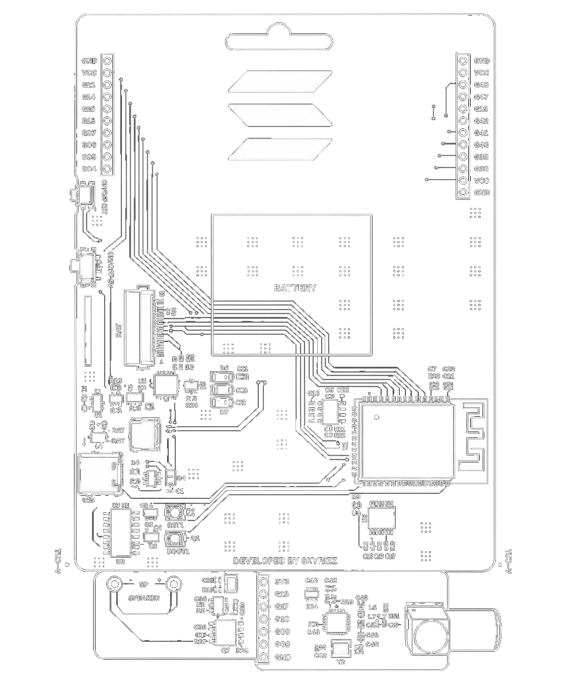
FULL SPECIFICATIONS
Everything on
the badge.
| MCU |
ESP32-S3-WROOM-1-N8R8 — dual-core Xtensa LX7, 8 MB flash, 8 MB OPI PSRAM |
| Secure Element |
Microchip ATECC608B — I²C bus, addressed via SE_EN (GPIO8) |
| USB / Serial |
WCH CH340C UART bridge with DTR/RTS auto-reset circuit |
| Display Socket |
24-pin SPI socket — BUSY, RST, DC, CS, SCK, MOSI on GPIO11–14, 17, 21 |
| Input |
6-button matrix via TCA9534 I²C IO expander (0x20), interrupt on GPIO1 |
| RF Module |
TI CC1101 — 315 / 433 / 868 / 915 MHz Sub-GHz, swappable |
| Audio Module |
NS4168 I²S amplifier + SPH0641 PDM microphone, swappable |
| I²C Bus |
GPIO9 (SCL) + GPIO10 (SDA) — 400 kHz, shared by expander and secure element |
| Power Gating |
SS8050 transistor on GPIO18 controls the peripheral VCC rail |
| Expansion |
28 accessible GPIO pins across dual 10-pin side headers (left + right) |
| Design Files |
KiCad 9.0.3 — full schematic, PCB, 3D model, Gerbers |
| Status |
Active development — open source, community welcome |
OPEN SOURCE
Full KiCad source.
Build your own.
Everything from schematic to 3D model is public. Production-ready Gerbers, BOM, netlist, firmware examples, and community mods. Read HARDWARE.md, PINOUT.md, and MODULES.md to get oriented fast.
github.com/OnionDAO-git/oniondao-badge →
- DIR hardware/
- ├── oniondao-badge.kicad_sch
- ├── oniondao-badge.kicad_pcb
- └── oniondao-badge.step
- DIR production/
- ├── gerbers.zip
- ├── bom.csv
- └── netlist.net
- DIR docs/
- ├── HARDWARE.md
- ├── PINOUT.md
- └── MODULES.md
GET IN TOUCH
Build the badge
for your next event.
Interested in a custom conference badge or hardware for your community? Get in touch — we handle design, manufacturing, and delivery.